
 EN

What Engineering Powers Cup Making Machine?
A cup making machine is not simply a fast folder. It is a timed forming system that turns preprinted paper blanks or a prepared web into usable cups by coordinating feeding, sleeve forming, seam sealing, bottom insertion, knurling, rim curling, and discharge. From a packaging-equipment selection perspective, the useful question is not just “How many cups can it make?” It is whether every station can repeat its task with the chosen paperboard, coating, cup geometry, and production rhythm.
That distinction matters whether you are evaluating a standard cup making machine, takeaway cup production equipment, or a cake cup making machine. The core engineering is similar, but tooling and process settings must match the product. Different formats can need different tooling, timing, or sealing settings.
The engineering chain inside a cup making machine
Most paper-cup lines divide the work into indexed stations. A drive system moves the work through those stations in a repeatable sequence, while mechanical tooling performs a controlled action at each stop. The exact layout varies by model, but the manufacturing logic is consistent: create a cylindrical body, close the side seam, attach and seal the bottom, finish the rim, then separate acceptable cups from the process flow.
In practice, the stability of a cup making machine comes from the relationship among motion, heat or ultrasonic energy, air or mechanical actuation, and sensing. One station can be well designed on its own yet still create defects if it is out of step with the station before it. That is why production teams should consider the machine as a synchronized system rather than a list of isolated components.
1. Feeding and blank control establish the starting position
Paper cup production begins with a blank: a cut sidewall piece that will become the cup sleeve. Feeders, guides, vacuum pickups, grippers, or servo-assisted mechanisms present one blank at a time to the forming area. A skewed, doubled, or late blank can create a poor side seam before sealing begins.
For takeaway cup production equipment, blank handling should be discussed together with paper stiffness, print registration needs, and the desired operating rhythm. For a cake cup making machine, the shape and smaller format may change how the blank is guided or supported. The relevant engineering question is whether the feed path controls the actual material you plan to run, not merely a nominal paper specification.
2. The forming station turns a flat blank into a sleeve
At the forming station, a mandrel or forming mould supports the blank while a mechanism wraps it into a cylinder or tapered sleeve. The overlap becomes the side seam. Accurate geometry depends on the relationship among the blank profile, mandrel dimensions, guide position, and closing force. Small positional errors can show up later as an uneven rim, a visible seam, or a bottom that does not seat consistently.
This is where tooling matters more than a generic speed claim. Cup diameter, height, taper, and material thickness all influence the forming condition. If frequent changeovers are expected, ask how the relevant moulds, guides, and adjustment points are managed. A changeover matters only if the forming position can be verified.
3. Side-seam sealing joins the cup wall
Once the sleeve is formed, the overlapping edge must be bonded. Depending on the cup stock and machine configuration, paper-cup lines may use controlled hot air, heated elements, or ultrasonic sealing. The engineering goal is a continuous bond without damaging the coating, distorting the sleeve, or leaving an unsealed path.
The suitable method depends on the coating, seam design, material behavior, and validation requirements. Operators need controllable process windows: enough energy and dwell for bonding, but not so much that the edge scorches, deforms, or becomes inconsistent. Sensors and control logic can prevent a missing or misplaced blank from receiving a full sealing cycle.
4. Bottom insertion and knurling make the cup functional
The next major engineering task is closing the bottom. A circular bottom blank is positioned beneath the formed sleeve, then the material is folded and compressed around the lower edge. Knurling creates a patterned, mechanically compressed seam that helps lock the bottom and sidewall together. Heating or ultrasonic energy may support sealing where the material construction requires it.
Bottom diameter, curl allowance, board thickness, coating response, forming pressure, and timing all affect this result. A stable bottom seam needs repeatable placement, matched tooling, controlled energy, and motion that does not disturb the cup.
5. Rim curling gives the top edge its finished form
After the body and bottom are complete, the upper edge is curled. The rim improves handling and gives the cup a consistent finished appearance; it can also contribute to how a lid fits where lidded cups are part of the intended application. Curling heads, guides, and cup support must align with the formed body. If the sleeve is not round or cup height varies, the rim station may reveal an earlier error.
Troubleshooting should follow the process path: an irregular rim can originate in feeding, sleeve forming, seam closure, or bottom seating.
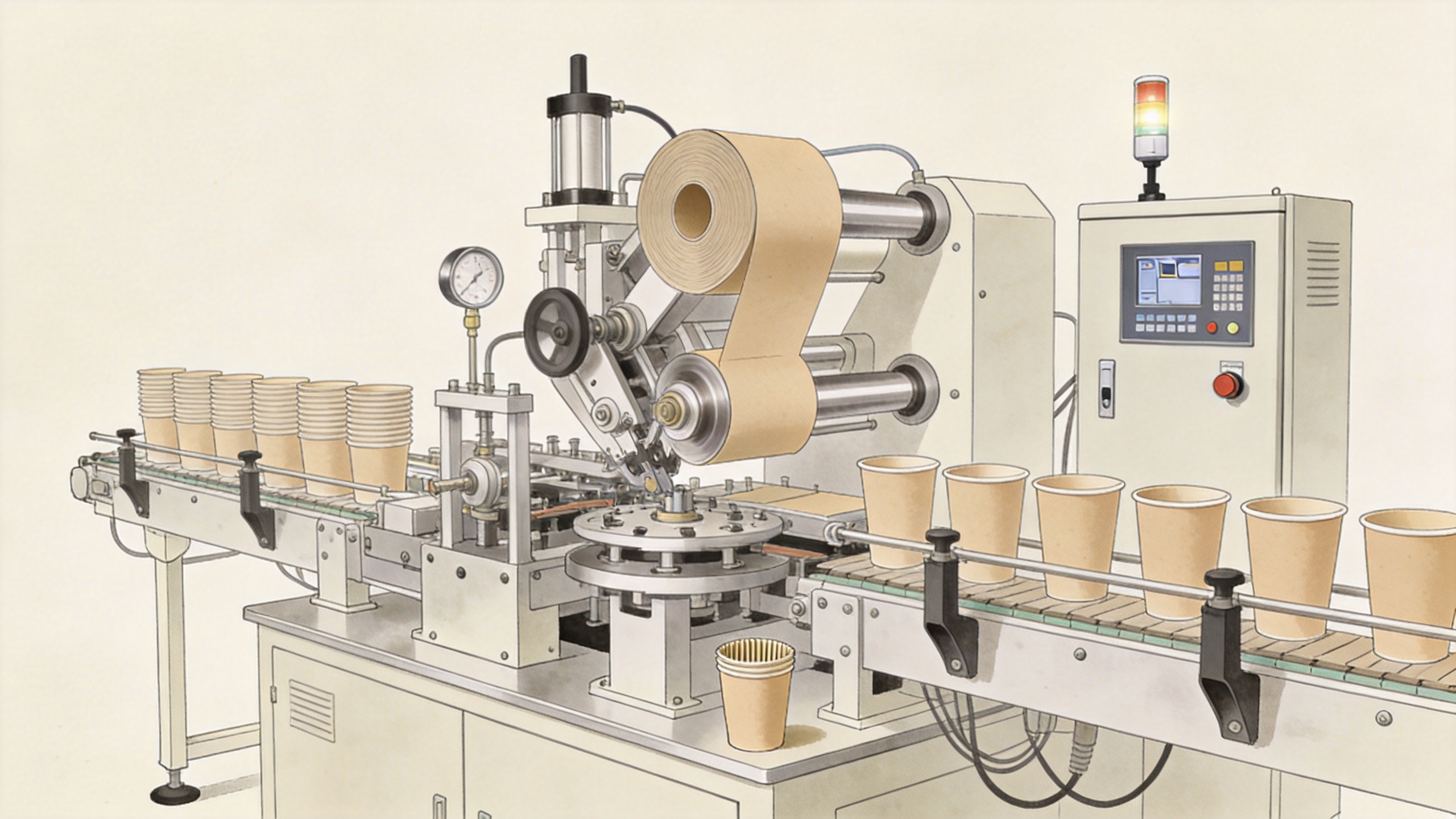
6. Drives, PLC logic, and sensors keep stations synchronized
The mechanical stations need an orchestration layer. A cup making machine may use a main mechanical drive, frequency-controlled motors, servo-driven axes, cams, pneumatic actuators, or a combination of these. The design choice affects how motion is synchronized, how adjustments are made, and how the machine responds to faults.
A programmable logic controller (PLC) coordinates the sequence. It can monitor safety conditions, trigger actuators, manage heating zones, count production, and stop or alarm when a sensor detects an abnormal condition. Photoelectric or proximity sensors may be used to confirm blank presence, cup transfer, or position. Servo-assisted feeding can improve timing, but only when machine, tooling, material, and setup are matched.
Think of controls as the system that protects repeatability. They do not eliminate the need for sound mechanics or stable material. Instead, they make the intended sequence easier to repeat and easier to diagnose when it changes.
What to verify before choosing the equipment
When comparing a cup making machine, begin with the intended cup—not the headline output rate. Confirm these points with the supplier and document the answers:
- Cup range: diameter, height, taper, bottom profile, and whether a cake cup making machine requires dedicated tooling.
- Material: paperboard grade, coating type, thickness range, blank quality, and the sealing approach suited to that construction.
- Production pattern: steady single-format runs versus frequent changes in cup size, artwork, or material.
- Control architecture: what PLC, sensors, drives, alarms, and adjustment methods are included, and which conditions stop the process.
- Acceptance method: how side-seam appearance, bottom integrity, rim form, and rejected cups will be evaluated under agreed material conditions.
- Support boundary: tooling list, spare parts, commissioning scope, operator training, and the information needed to troubleshoot a process issue.
Why production speed is only one engineering output
A published rate describes a potential operating point, not an automatic guarantee for every cup. Actual output can be influenced by cup geometry, board behavior, changeover frequency, quality criteria, operator practice, and how consistently blanks arrive at the feed station. A sound engineering discussion therefore connects output to the conditions used to verify it.
This approach is especially useful for buyers of takeaway cup production equipment. A line intended for long, stable runs may be configured differently from one that prioritizes a broad mix of cup formats. Neither objective is inherently better; the configuration must serve the operating plan. Before comparing quotations, turn the intended cups, materials, and inspection expectations into a shared technical checklist.
Conclusion: engineered repeatability is the real power source
What powers a cup making machine is a coordinated combination of tooling, motion, controlled sealing, forming pressure, sensors, and PLC logic. The equipment makes a cup only when those elements arrive at the correct place and time for the selected material. Start with the final cup and work backward through the process: blank control, sleeve geometry, seam bonding, bottom knurling, rim curl, and inspection. That is a more reliable way to specify a cup making machine than comparing speed in isolation.
Before requesting a configuration, prepare sample cups or drawings, material details, desired cup range, expected changeover pattern, and acceptance criteria. These inputs keep technical discussion and commissioning focused on verified conditions.
 ONLINE